
I says to my wife, I says:
Dear, this new project is going to bring tears to your eyes, it’s so cool!
She’s shaking her head and says to me:
Oh, I’m crying alright.
She’s not a believer in my latest wacky electronics project — the Traffic Light Parking Assistant. 1TLPA from here on out I believe her hesitation to accept this project stems from an early project proposal on my part. It went something like this:
Dear, wouldn’t it be great if we had an automated electronic contraption that told us when to stop after pulling into the garage?
She probably took offense at the implication, i.e., that she was a bad parker. In fact, it is I that needs this contraption more than she. She has her own methods for parking consistently. 2For instance, she, being the smart practical type, uses various reference points in the garage to gauge how far to pull in. I, however, have the curse of an engineer. Which is to say, I am always plagued by the subconscious question, “How can I make that process better?” Which is almost always followed by the secondary electrical engineering question, “How can I add blinking lights to that?”
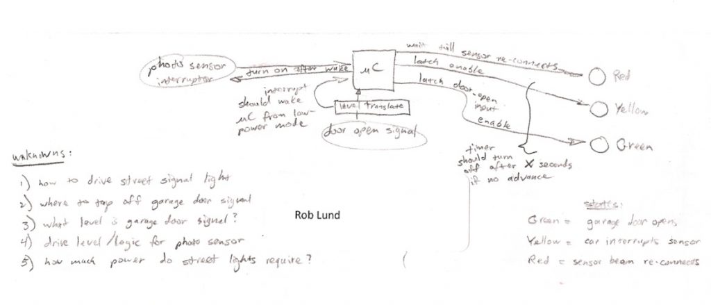
To start this right, I composed my system block diagram 3Every engineer worth his salt starts with one, which defines all the inputs and outputs of the system. Think of the block diagram as a mission statement for the project. Below is mine:
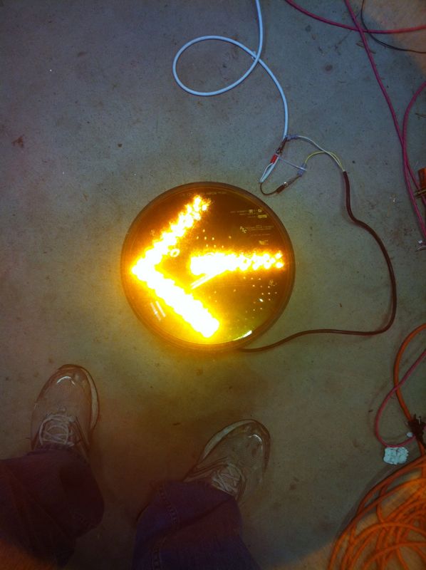
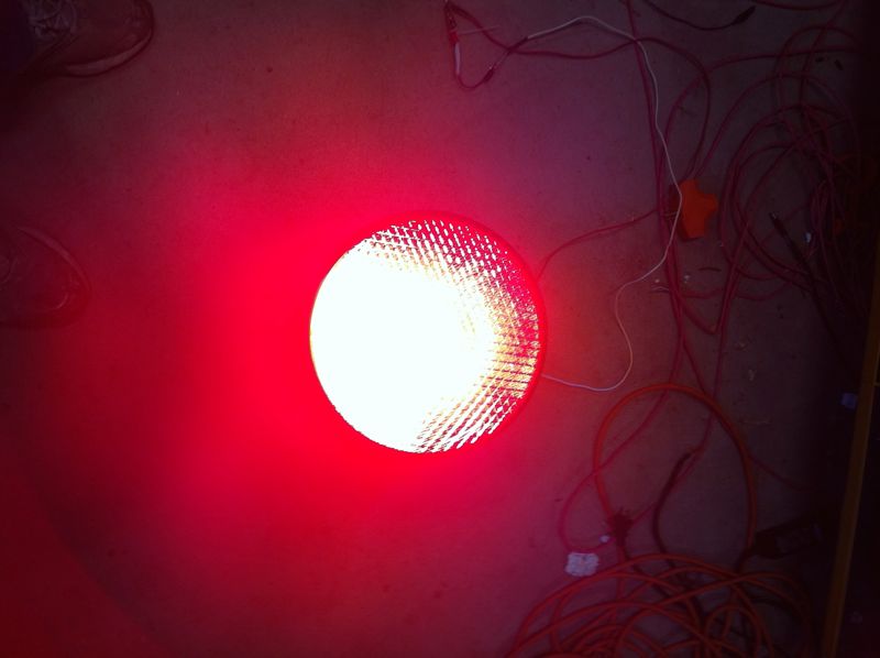
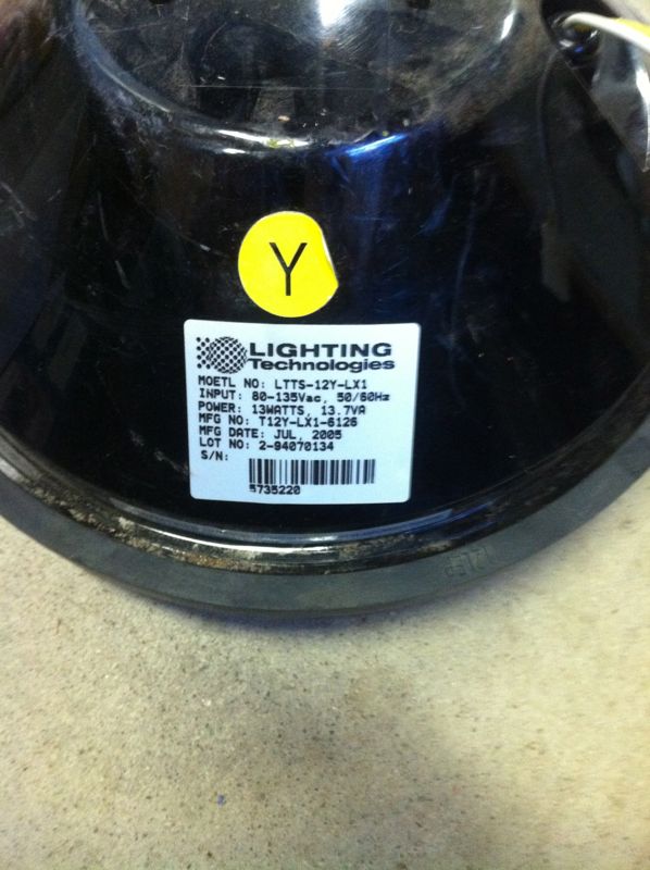
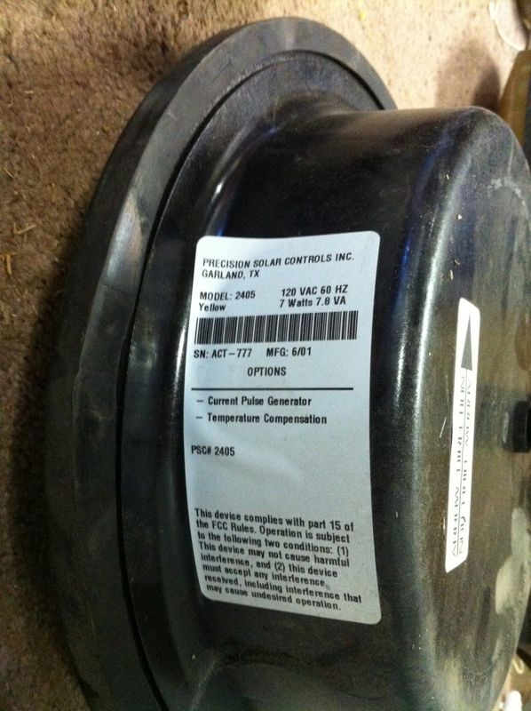
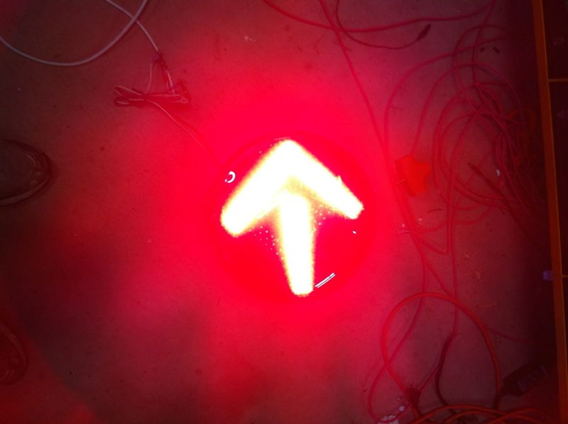
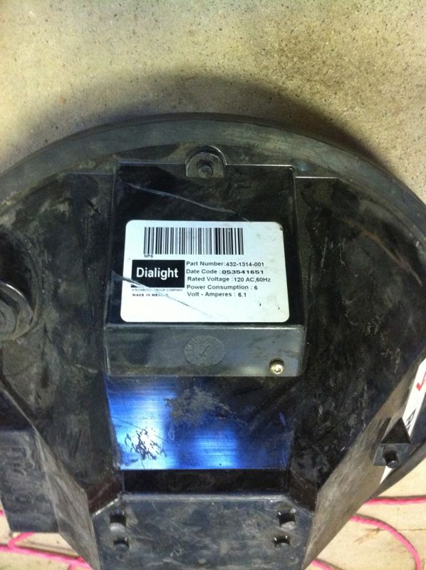
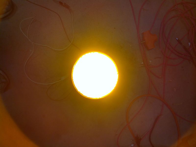
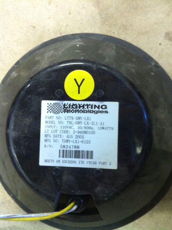
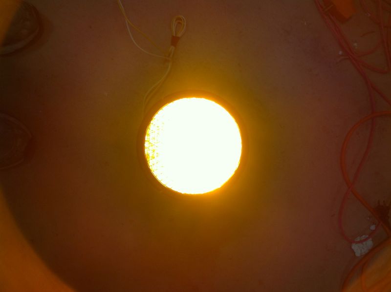
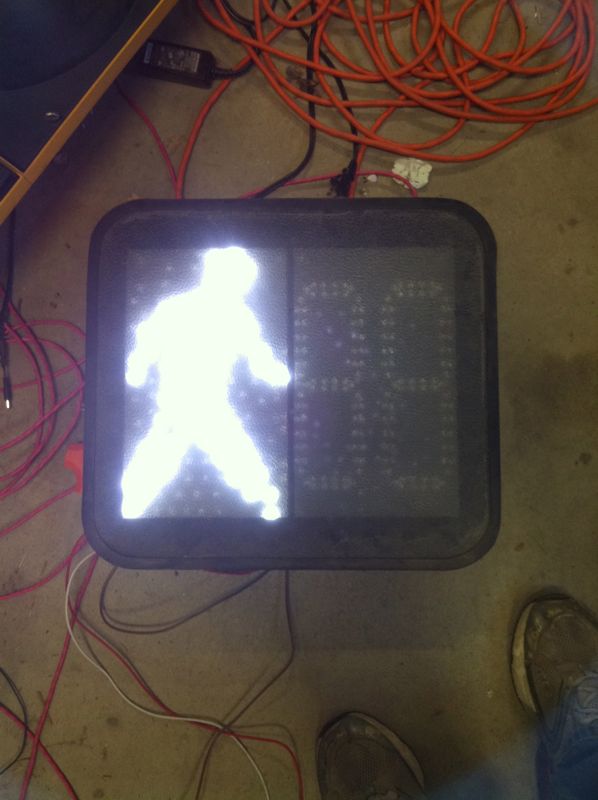
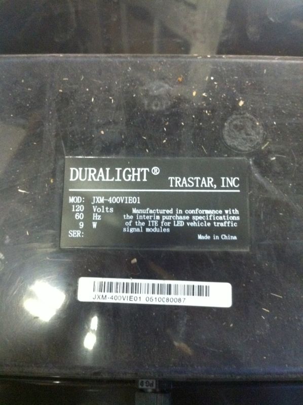
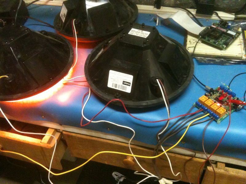
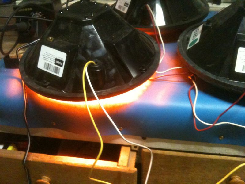
So with that bit of project genesis, I set about making the TLPA. I should add that I’ve never been all that obsessed with traffic lights, per se. I just thought that they would be the ultimate indicator for said parking. What better real-world indication is there, but with traffic lights? Red means stop, green means go. With that modest proposal, I set about finding these traffic lights. After some digging, I came across a government surplus website, sort of an eBay for Big Brother. My home town had several auctions for obsoleted or retired traffic lights. I bid on one and won for a song — about $15 for an entire lot, which turned out to be something like 40 lights! Sadly, there were no school-bus-yellow boxes for the lights. The auction was just for the indicator lights, all 12″ diameter, gorgeous LED lights. I filled my entire car getting them home! Here are several of the lights:


Next, I found a really nice I/O module from SparkFun. They are a Boulder, CO based electronics hobbyist company. 4what Radio Shack used to be They carry a ton of neat products and have a fantastic website. For my project, I knew that I needed at least 3 opto-coupled inputs and 3-4 relay driver outputs. Wouldn’t you know it, SparkFun makes just such an animal for only $34! I couldn’t build that from scratch for that price. And right now, with a 6 month old baby at home, time is an absolute premium!
This I/O board is designed to be driven by an Atmel microcontroller, the ATiny2313. My comfort level is Freescale (aka Motorola), though I’ve always wanted to break into the Atmel world. But with any new platform, there is a corresponding new tool chain 5In other words, the software tools and licenses, the hardware programming cables, the simulators and hardware debuggers, etc. to become acquainted with.
In the interest of time, I opted to stick with what I knew. I settled on the MC9S08SH8. It’s a nice micro from Freescale that is +5V compatible (which is a requirement since the AVR IO board is regulated at 5). The SH has enough I/O pins, and it comes in DIP 6Dual Inline Plug, not many do anymore, you know. The hardest part about this choice was adapting the AVR IO board to work with a much different pinout of the Freescale.
Do achieve this, I simply made an adapter using a DIP plug 7available at Digikey and an old HDD 8Hard Disk Drive 50-wire IDE cable. I soldered the required pins of the cable onto the DIP plug, which only turned out to be 5 or 6 for the following demo.
On the microcontroller end, I used a DEMO9S08SH8 board as my hardware development platform for a few reasons:
- The board contains the same target micro that I’d be using when I “release” the design, so to speak.
- Therefore, I can use the DEMO board as a “production” programmer. Less tools in the tool chain, the better.
- The DEMO board has an onboard USB subsystem, from which I can program the micro and do hardware debugging.
- The DEMO board has a full and convenient DIP I/O section from which to break out the required I/O lines to the AVR relay board.
Here are some pictures of this stage of the software development:
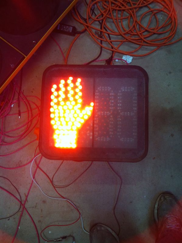
Partial Project Gallery:


For a demo of der blinkenlights 9A very early hacker term, referring to a pseudo-German warning label found on computer servers in the 60s. See Wiki for the entertaining story, check the video 10ElectroLund is getting into the modern era with the help of my iPhone below:
Footnotes
- 1TLPA from here on out
- 2For instance, she, being the smart practical type, uses various reference points in the garage to gauge how far to pull in.
- 3Every engineer worth his salt starts with one
- 4what Radio Shack used to be
- 5In other words, the software tools and licenses, the hardware programming cables, the simulators and hardware debuggers, etc.
- 6Dual Inline Plug, not many do anymore, you know
- 7available at Digikey
- 8Hard Disk Drive
- 9A very early hacker term, referring to a pseudo-German warning label found on computer servers in the 60s. See Wiki for the entertaining story
- 10ElectroLund is getting into the modern era with the help of my iPhone
Leave a Reply