
My garage has a single light switch in it for its overhead fluorescent lights. This light switch is not conveniently located; it is situated beyond our freezer, such that one has to walk into the darkened garage in order to turn the switch on. So I made an electronic 3-way switch. “Why?”, you ask. Indeed. My reasons are always convoluted and sometimes irrational. Best not to ask such questions.
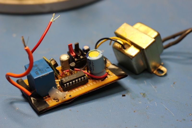
But if you must know, our garage is mostly finished with drywall, so adding a second “3-way” switch would have been difficult. I opted for an electronic switching circuit. 1My method involves relays, an AC to DC power supply, some digital logic, and momentary switches. The advantage to this circuit is that you can ostensibly have as many switches in parallel on the same circuit. This is known as a “multi-way” circuit.
First, start with the napkin diagram:
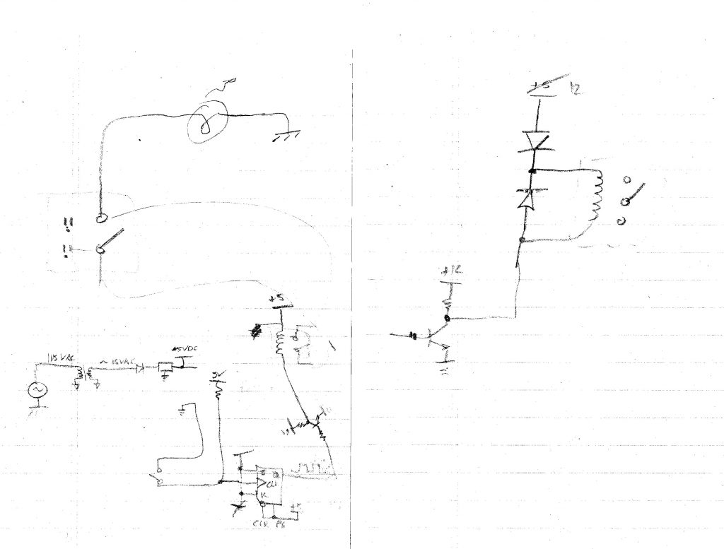
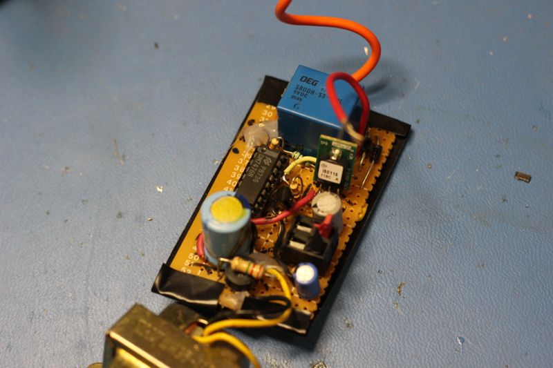
The core of the design revolved around a JK flip flop. Rockin’ this project with 30 year old technology.
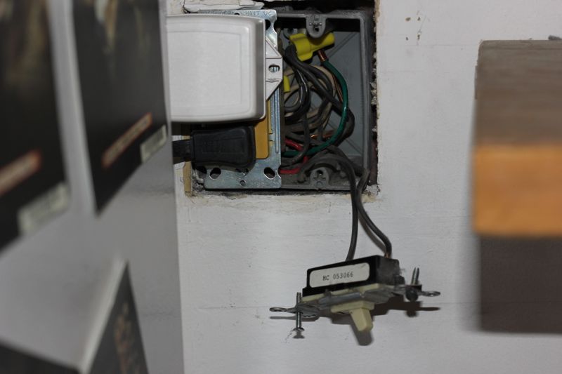
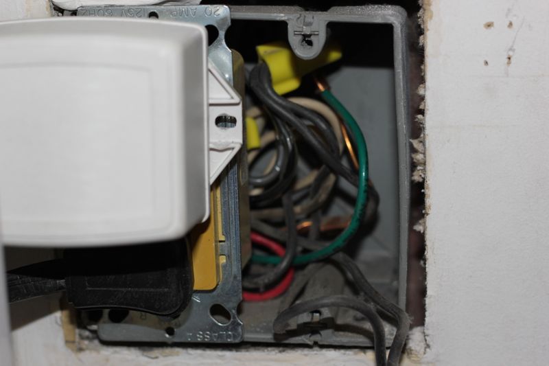
For the mechanical switch, I removed the AC switch and used a surface-mount garage door momentary contact switch. The wiring then can also be garage door opener grade, small current wire (since this input to the circuit is on the low-voltage digital logic chip).

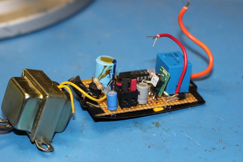
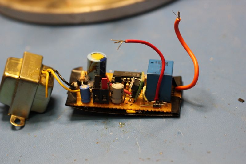
Here are some photos of the final project:
Full Project Album
Footnotes
- 1My method involves relays, an AC to DC power supply, some digital logic, and momentary switches. The advantage to this circuit is that you can ostensibly have as many switches in parallel on the same circuit. This is known as a “multi-way” circuit.
Leave a Reply