
Tag: solder
-
TV repair
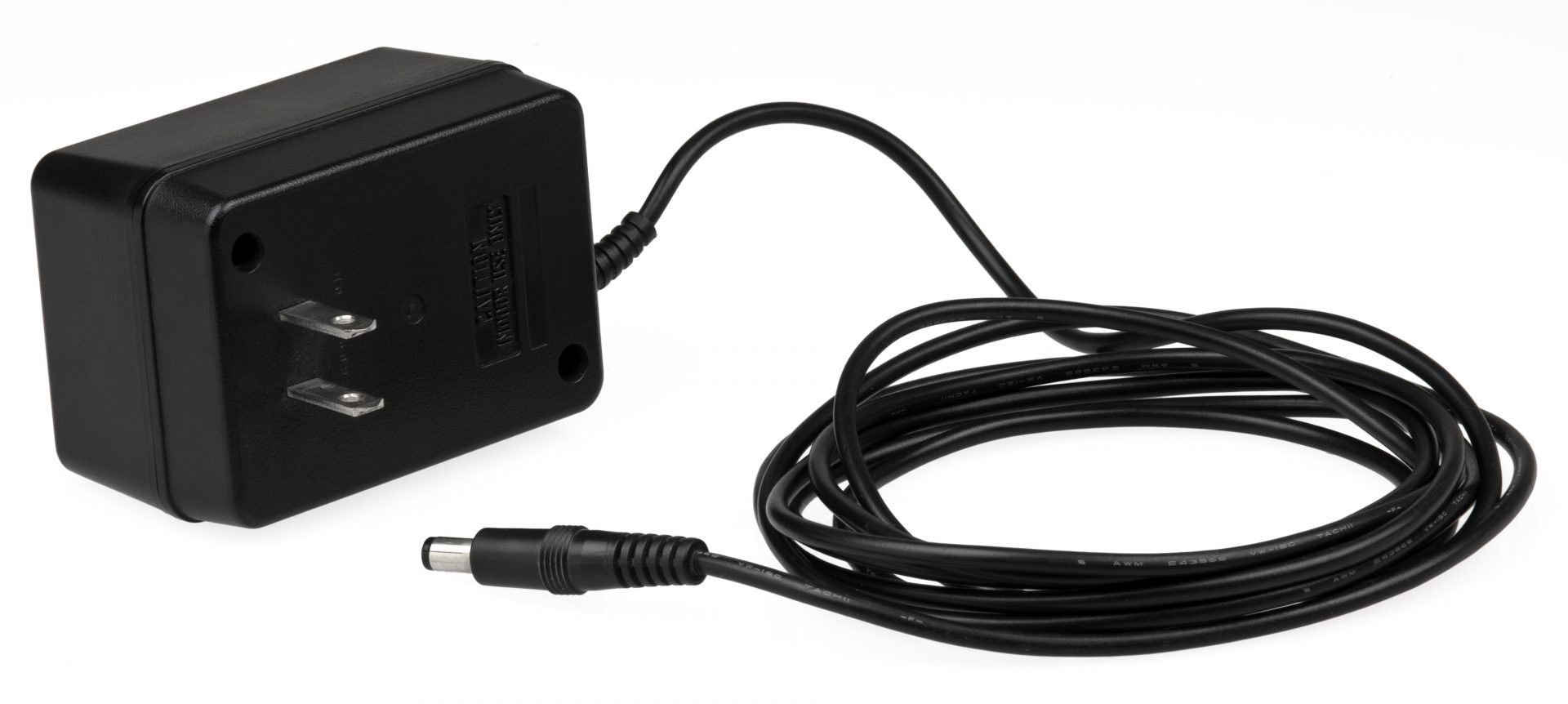
A few months ago (ok, maybe years), I scored a free TV off a Facebook neighborhood group. It’s a Samsung 40″ LCD. Not very new, but hey free is free. The giver warned me that it “needed a new power cord,” or so they said. I was puzzled, but then took this as their own…
-
Chicken coop door circuit
So I’ve been updating my chicken coop lately. See here for one such recent upgrade: The latest upgrade is a two-fer design… Door State Indication I want to be able to tell, from a distance, that the door is either open or closed. This is both a convenience to the chicken ranchers and a safety…
-
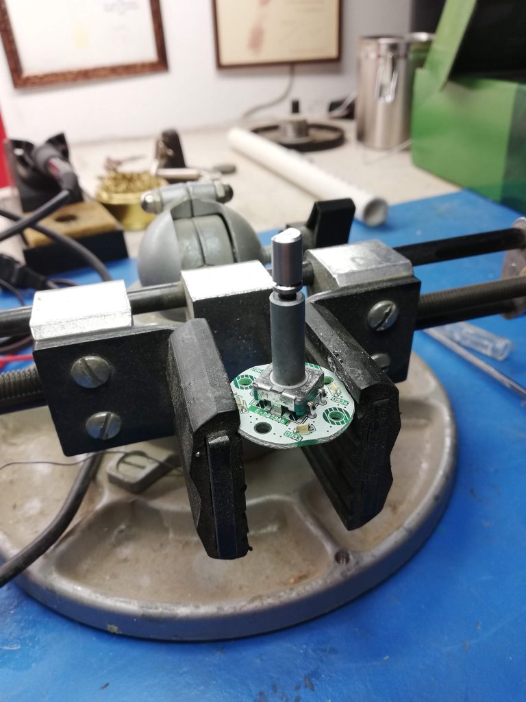
Digital volume knob fix
The volume knob in my wife’s Toyota Highlander behaved weirdly. As you turned it up or down, the volume setting would jump up or down, sometimes in the wrong direction and by an unpredictable amount. It didn’t give a linear output as you would expect. What to do? Why, take it apart of course!
-
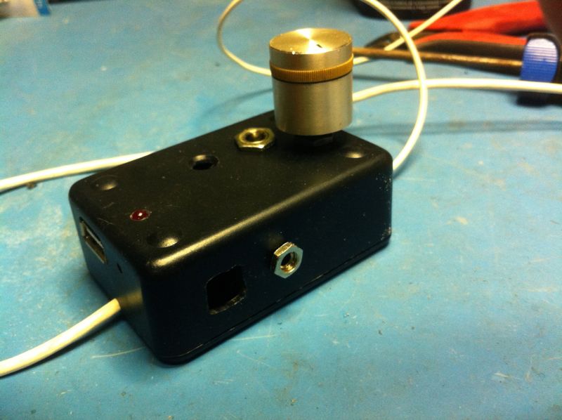
Cordifying battery things
In my house, we have a ton of “batteried” devices. Having small children, in this modern age, one tends to collect a lot of toys, tools, crafts, and associated appliances that require an array of batteries. Triple- and double-As are in high demand, though 9V and even the C cells are occasionally used. Don’t even get…
-

GaSiProMo
I’m a notorious task-starter, and not a great task-finisher. My garage is littered with old projects that are collecting more dust than accolades. I can lean on the old, dependable excuses but really that’s lame. If every moment is the new normal, then there aren’t any excuses. Our hobbies define us, and I love my…
-
Inaugural Maker Faire
Well, I’ve officially joined the DIY electronics community. Last week, I attended my first Maker Faire. It was my city’s first ever, and I was determined to take one of my projects as a booth participant. Nothing like a deadline to get my hind quarters into gear and (kind of) finish a project!
-
Dell OptiPlex motherboard repair
My office was liquidating a bunch of old computer equipment. In the heap, my eye was caught by a Dell box. “Hmm, what’s wrong with that computer?” And so began my next big obsession.
-
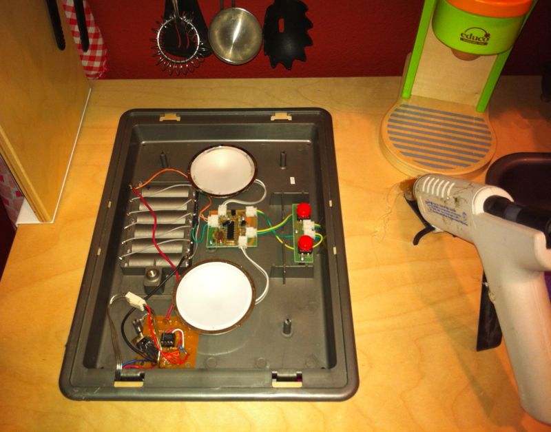
IKEA kitchen light mod, part 2
A while ago, I modified my daughter’s little kid kitchen. In that project, I found my design self teetering on that edge between two goals: get-it-done on the one side, do-it-right on the other. I had chosen the former and even my 2 year old (at the time) could see that this was a critical…
-

Cell phone connector fix
My good friend James contacted me with an electronics problem. Seems his daughter’s cell phone was on the fritz. So I agreed to take a look. She has a Pantech P7000 flip phone, but it stopped charging. I asked a few questions first to understand the nature of the problem. For instance: James gave me…
-
iPod jukebox (phase 2): prototype
You remember the first phase of the iPod jukebox, yes? To jog your memory, the basic goal was simple. How do I make these dust-collecting components: …work with my iPhone in order to have music in my workshop? Simple concept, not so simple electronics. The project is mostly a connectivity issue, i.e., there are tons…