
My wife just got a Subaru Outback 2.5i station wagon. She’s in love with station wagons. No, seriously. Station wagons have been her dream car body style forever. It’s like she’s been a stereotypical soccer-mom-in-training since high school. That said, by her account I drive a station wagon too. I’m not going to split hairs with her. Tomato, to–MAH-to.
Anyway, in Sarah’s previous car 1a VW lemon if there every was one, sorry dear — which goes without saying was a station wagon — she used one of those Belkin iCarPlay iPod FM transmitters to get her iPod music into her factory stereo receiver. Since getting the Outback 2which the cool kids call the “Subie OB”, I jumped at the chance to do this right. That is to say, get a better sound quality input into her car’s factory stereo.
Of all the methods of getting your iPod output into your car stereo, those FM transmitters are probably the most painless. Plug it in and away you go. But some cars vary, and the transmitters certainly vary. Her Belkin is one of the best transmitter solutions I’ve seen. And yet, the same transmitter in my car was pretty crappy — lots of static. I chalked it up to a weaker antenna on my Toyota Matrix.
I’d say that the order of iPod integration into car audio systems ranks like this (most ideal and best audio quality to least):
- iPod connector/charger dock right on the car stereo (best sound quality, plus some control of the iPod through the car stereo; only available in newer factory stereos, or after-market stereos)
- Auxiliary input jack built into car stereo (usually an 1/8″ audio jack, CD quality sound, but no iPod control)
- After-market auxiliary input via either:
- CD changer input connector (CD quality sound; downside is you lose the future option of having a CD changer)
- Custom auxiliary input boxes (near CD quality sound; but these vary wildly for each car manufacturer and tend to be labor intensive)
- FM modulator boxes (couples audio signal from iPod onto FM antenna input of the car stereo; sound quality is always FM broadcast strength)
- FM transmitters (audio quality is always a little less than FM due to signal strength)
Her year OB has no built-in auxiliary input, and there are limited choices for after-market auxiliary input solutions. Subaru was pretty late to the game of iPod integrated solutions, their 2008 models being the first.
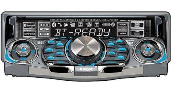
Sure, there’s much easier approaches to integrating an iPod. We could go with an after-market stereo and get the best sound quality and tightest iPod control integration. But Sarah’s been wisely avoiding that route. I tend to agree with her: have you noticed the goofy trend in car stereos? There’s enough high-color display bling to distract the most attentive driver. And what’s with having DVD players now? It’s bad enough that people talk on cell phones and drive (myself included). Now they’re watching movies too?!
So anyway, my job was to come up with the best sounding solution, given her preference of the factory OB stereo. My own constraints were to:
- use as few new components as possible and consume from my growing electronics inventory (translation: junk)
- package the solution such that it’s ergonomically and esthetically pleasing
- make it practical and unobtrusive
I decided to go the route of an FM Modulator. The Scosche FM-MOD01 is highly rated on Crutchfield and did what I wanted. It works by splicing into the FM antenna input of a factory stereo and modulates any after-market audio output onto the FM line. You get a radio quality sound that way. I found one pretty cheap on eBay for $18 bucks delivered.

The funny thing about these modulators is that they have a switch. At first, I assumed this was to simply switch the antenna circuit on and off, thereby disabling the modulator’s output. But no, the switch was wired into the power input of the modulator. That’s odd to me, because the modulator has an antenna input and output cable for the splice. Wouldn’t turning the modulator off also disable this antenna splice, in turn disabling the car’s antenna? Turns out, this isn’t so. I did some probing and found that with the power switch on or off, there was continuity between the antenna in and out cables. It seems that this is a hard wired connection inside the modulator. So when the modulator is on, the auxiliary audio signal (our iPod) piggy-backs onto the car’s antenna and spits out onto FM 87.9 (there are two selectable frequency outputs). If there’s a station already at that frequency, I guess the modulator overpowers it (if not, you’d have to switch the modulator to its second frequency setting).
My first design challenge was to eliminate the need for a switch at all. It makes more intuitive sense to simply plug the iPod in and start using it. I knew enough about the iPod connector from a few other projects to know that there were extra ground pins. So I planned for a simple active-low transistor power circuit. I had a spare 555 timer chip which I used for hysteresis (prevents “relay chatter” during the instance of inserting the iPod).
I drew up a system block diagram of the circuit and proceeded to breadboard the circuit:

It’s a mess, but it works! Now, we have to start packaging the circuit, which in my opinion is always the most difficult step in any electronics project. It’s one thing to design a circuit — pencil to paper is easy. It’s another step to make a prototype on breadboard or protoboard. But it’s another thing entirely to package a circuit into a nice box, preferably as compact as possible. A lot of thought goes into how the circuit will layout and cables will route for optimal space savings.
It’s precisely at this step that my personality, already predisposed to arcane details, kicked in big time. I started out this whole project with the preconceived notion that I’d use an old iPod dock we had quit using as the form factor for this circuit. My feeling was that this could be located inside the arm rest compartment of Sarah’s OB. Dock the iPod, select your music or podcast, and stow it away until later.
Well, that was all fine and good, but that’s not how Sarah uses her iPod in her car. Sarah prefers the paradigm of having the iPod on a cable, like the Belkin transmitter. It’s plugged into the car at one side and she can pull it out of a compartment and adjust it while she’s driving.
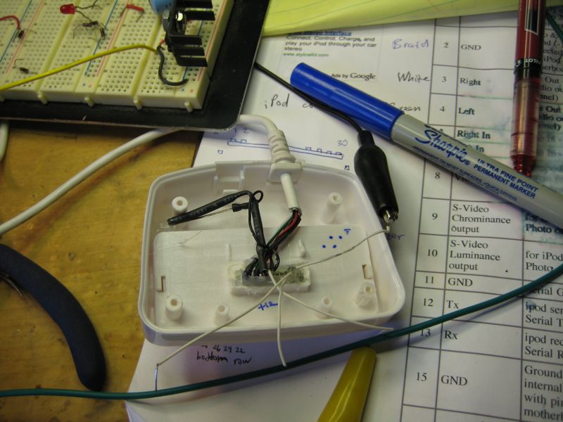
But this is what happens when the engineer is also the product developer. He gets so absorbed in the minutia of design that he loses sight of practicality. Oh, it might be a really cool gizmo with lots of capability, but it’s as ugly as a brick or completely unusable. Yeah, that’s me. You see, I built this whole thing with my paradigm in mind and it didn’t even occur to me to ask her how she wanted to use the thing! Here is the evidence:

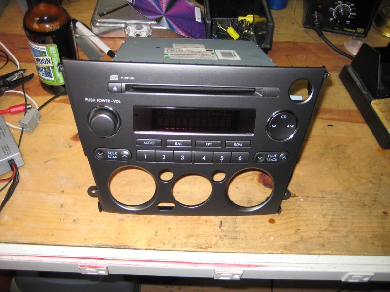
Pretty, huh? That white case is the old iPod dock housing. I popped it open and found the pins on the iPod connector that I needed: Firewire power (+12V, GND), right / left audio, and a spare ground (for the modulator power enable). Soldered the whole thing on a small protoboard, cabled it all, and did a final test.
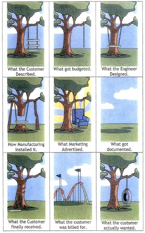
At this point, I finally approached Sarah rather triumphantly with the circuit (thankfully before doing the final install in the car!). She rather gracefully let me down easily. This is why marketing departments exist. Someone has to actually talk to the customer to find these things out beforehand! This experience reminds me of a great comic strip that sums up product development well:
So, it was back to the drawing board. Actually, I didn’t have to start completely over. I already had the circuit done. I only needed to:
- repackage the circuit into a new form factor
- find a new cabled iPod connector
But #2 was already done — her old Belkin transmitter! The only problem with that was the thing had developed a bad connection over the years. It’s left or right audio (can’t remember which) was becoming intermittent. I tore that apart and found the problem. One of those wires had broken inside the cable somewhere. So I desoldered the Belkin cable and replaced it with an old USB cable. And since the cable is black like the Belkin, you can’t tell it was repaired. Also, this USB cable had one of those molded ferrite beads impregnated in the cable. This was a nice bonus, since magnetics are a great way to decouple ambient RF noise 3automobiles are notorious for being “noisy” environments electrically, mostly from the alternator.
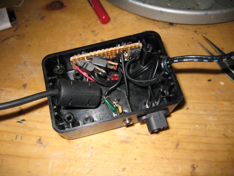
Next up was repackaging the circuit into a new box. I chose a simple black plastic project box. You can get these at any Radio Shack.

You’ll notice that on one side of the box is a DC power jack and an 1/8″ audio jack. These are outputs to the modulator, which I put behind the stereo. More on that in the install section below. The other two cables can be seen below:

One is the refurbished Belkin iPod cable. The other is power input to the system. I’m using an old cigarette lighter power plug which happened to have an integrated quick-blow fuse. This turned out to be a nice addition, because the modulator had its own inline fuse on its power wire. I removed that one since this cigarette lighter plug has one.
Here, you can see how I stuffed the USB’s ferrite bead into the box, further simplifying the clutter.

Here’s the top side of the box. I added two LED indicators. The red one is for power. The green one lights up when the iPod makes connection. My main reason for having both indicators is for troubleshooting. If this box fails in the future, it would be helpful to know what portion of the circuit failed. Is the unit getting power? Check. Does the circuit recognize the iPod? Check.

Now it’s time to tear apart Sarah’s new car. Never fear, I have the internet. A great source of info was the SubaruOutback.org user forums. In particular, the first half of this howto was vital to getting the factory stereo out. 4compliments of Jazzy Engineering Though not completely thorough (there were a couple steps I had to improvise), it was a godsend. Holy crap, cars these days are amazingly complicated to dismantle!
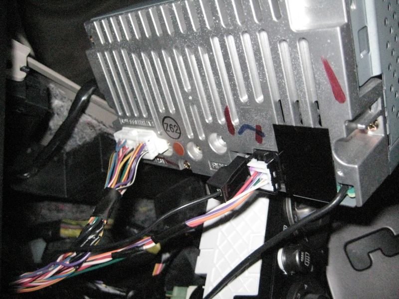
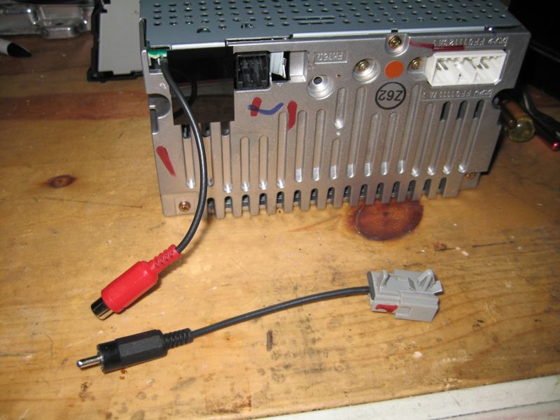
So here is the back of the stereo. I’ve got it annotated to clear up some questions I had:

That chassis ground lug was so firmly connected, I had to destroy the plastic shroud in order to get it off.

The antenna wire was another shocking discovery. Subaru, in all its wisdom, decided to hard wire the cable into the radio. Can you believe that?! Probably 90% of radios out there, both factory and after-market alike, have the standard Motorola style coax connector. That’s exactly what the modulator box has. Instead, the OB has this “pigtail” antenna cable that goes to a custom plastic connector.

Now, you can buy adapter cables for the OB stereo. Here’s the male, and here’s the female. But why buy yet another set of cables, creating more bulk to then tie-wrap down somewhere under the dash when you can just make your own?!
I used some old male/female RCA cable connectors:

The color combinations are a bit odd, but these were all I had on hand. In the above picture, I spliced in a male and female mated pair so that the original cable can be restored and the modulator removed in the future. Then on the modulator, I clipped off its Motorola connectors and put matching male/female RCA’s. Here is the stereo and modulator, all mated together:

Next up is installing the modulator somewhere behind the radio. I chose one of the chassis supports. It’s a nice big chunk of metal, not to mention a great source of ground plane. I zip-tied it to this bulkhead:

Here, you can see where I routed my cables from the modulator back down to the arm rest compartment. I used a coiled plastic cable sheath to protect the cables. I picked this up from Radio Shack as well.

Below the shift knob, the cable continues to route underneath the center console. I tie-wrapped it to another cable. At this point, the cable has to get inside the arm rest compartment, which thankfully is all plastic. I opted for drilling discretely into the bottom left corner of the compartment. The perspective below is looking outside of the compartment:

Here’s the view looking into the compartment, looking down from the driver’s seat:

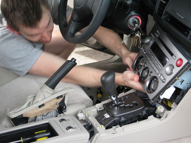
Here I am installing the beast back into the belly of the whale 5my lovely wife Sarah took the picture:

And here is my helper technician. Royal, the dog, loves taking car rides. He loves them so much, in fact, that he will gladly hop in the car with Dad, even if the car doesn’t actually move!

Project Gallery:

Footnotes
- 1a VW lemon if there every was one, sorry dear
- 2which the cool kids call the “Subie OB”
- 3automobiles are notorious for being “noisy” environments electrically, mostly from the alternator
- 4compliments of Jazzy Engineering
- 5my lovely wife Sarah took the picture
Leave a Reply to Sarah Cancel reply